 |
High Paying
US Jobs, Economic
Empowerment
&
Revitalization
of
States through Federal Power |
"Critical Field"
Technology Innovation
&
Maximized Profits on
R&D and Investments |
Prevention of Biochemical
and Nuclear Proliferation
&
Homeland Security
Technologies |
Highest
Resolution Holographic Subsurface Radar
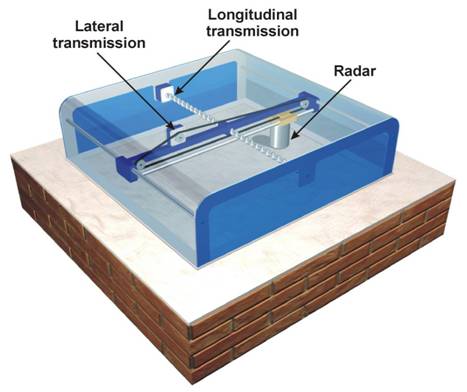
Fig. 3. Arrangement of objects
in the mockup wall
The distinctive features of the radar:
-
Ability of executing one-sided sounding of a wall, instead of
double-sided sounding as X-ray apparatus does
-
Ability to find out not only metal objects, but also non-metallic ones
-
Safety of radar's using for operator.
The Radar can be used in the following areas:
-
Airport Luggage Scanning
-
Counterintelligence activities for detecting bugging devices
-
Inquiry activities of law-enforcement agencies
-
Inspection of building structures for determining the position of
reinforcement, voids and other heterogeneities
-
Surveying of especially critical constructions (airport runways,
bridges, etc.) for determining their latent flaws
-
Detection of cracks in underground parts of buildings and structures for
prevention of the water infiltration.
ABSTRACT

A subsurface radar using a multifrequency signal has been developed. It is
designated for surveying building structures and works. The characteristic
feature of this device is the possibility of obtaining sounding plane microwave
images featuring a high resolution attaining 1...2 cm. T he main applications of
this device include the survey of building structures to reveal their
heterogene-ities and defects and the investigation of premises to detect bugging
devices.
Key words: building structure, defects, heterogeneities, microwave
images, subsurface radar.
INTRODUCTION
The existing methods of the nondestructive testing of building structures have a
number of deficiencies. For instance, X-ray devices require two-side access to a
building, which is difficult in some cases or most commonly impossible. However,
X-ray equipment has found a wide application in medicine, for baggage checking
at airports and in those technological processes where the two-side access to an
object under investigation does not produce any problems. Ultrasonic equipment
proves to be inefficient in media containing a great number of microcracks and
heterogeneities. Its field of application includes the study of continuous and
relatively continuous media involving a small number of defects and allogenic
inclusions. From this viewpoint the use of the RF range appears to be most
promising because reflection sounding is possible, i.e. the receipt and
radiation of RF waves is performed from one side of a surface sounded. This
allows for examining walls, ceilings, enrichments, etc. in finished buildings.
Thus, the quality control of their construction and repair is possible. The
proposed method using a specially made antenna permits the survey in corners
between walls, which is hardly feasible by using other techniques. A further
advantage of radar sounding is a relatively long wavelength lambda
within the microwave band used because this wavelength does not produce
reflections from insignificant natural heterogeneities such as cracks and the
operational hollows of bricks and other building materials which are small as
compared with lambda.
Recently short impulse time domain subsurface radar systems
have already found applications for sounding various building structures and
coverings both for detecting hidden objects in them (Botros et al., 1984) and
for defect diagnostics (Carter et al., 1992; Maierhofer et al., 1996;
Papaioannou et al., 1996). The sounding of building structures presents certain
difficulties, because the required resolution is very low and ranges from 1 cm
to 5...10 cm depending on a problem to be solved. These resolution requirements
are related to the characteristic size of heterogeneities, which are found in
different building structures.
Especially high requirements arise when detecting various
bugging devices hidden in the walls or the enclosures and enrichments of rooms.
The size of these devices is very small and their design is such that they are
difficult to be detected against the background of reflections from the natural
heterogeneities of building structures. These heterogeneities can include steel
reinforcement bars of concrete, pipes and electric cables, fastening nails and
clamps, etc.
The resolution of subsurface radar has conventionally been
improved by reducing the pulse duration in pulse radar or by widening the
frequency band in FWCW radar. However, these measures result in more complicated
and more costly equipment used for this work.
The building structure sounding radar discussed in this paper
operates on several fixed frequencies, and a signal is received by using two
cross polarizations on each frequency. Microwave images obtained have a high
resolution in the sounding plane of the medium and allow for restoring the shape
of objects by which assumptions can be made as to their nature and purpose.
SYSTEM
The general view of RASCAN radar developed in TsNIIRES is presented on Figure 1.
This is subsurface radar using a signal whose frequency varies according to the
step law.
The radar includes a transmitter radiating on 5 frequencies
within the 3.6 GHz to 4.0 GHz band and two receivers operating in the same
wavelength band. The transmitter power is below 10 mW. The antenna of one of
these receivers has the same polarization as the transmitter antenna has. The
antenna of the other receiver effects cross-polarization reception. All the HF
elements of the radar are mounted on an antenna unit and accommodated in a
common body. The HF part of the radar is shown in the foreground of the picture
on Figure 1. It is connected by a LF cable to an interface unit, which in turn
is connected to the parallel port of the computer. And the computer itself does
not require any modification except for installing appropriate software. The
interface unit and the computer are shown in the background on Figure 1.
Microwave
images are obtained by the mechanical scanning of the antenna unit over the
surface of an object under sounding. The rate of scanning of the surface
investigated is that which allows for taking the image of 1 m2 of the
surface over the time interval from 5 min to 20 min. depending on the required
space resolution. The levels of received signals are measured every 1 cm or 2 cm
both along the X - axis and the Y - axis. A simplified block diagram of the
radar is shown on Figure 2. Data was entered into the computer through a
specially developed interface, which was connected, to the parallel port of the
computer.
When taking measurements, the oscillator was switched serially
from one operating frequency to the other one (f = 3.6, 3.7, 3.8, 3.9, 4.0 GHz).
The frequency choice was in agreement with the requirement of changing the
contrast of any object in respect to the background level at the boundaries of
the frequency band. This is especially important for performing measurements in
heterogeneous media and makes it possible to provide a sufficiently contrast
observation of an object if only for one of the frequencies and, as is shown
below, allows for detecting objects placed in the same line of sight but at
different depths.
The electromagnetic radiation is reflected from objects
possessing the dielectric permittivity contrast in respect to the medium in
which they are located. By virtue of this fact obtained images show not only
metal objects but also dielectric heterogeneities, e.g. voids, which
distinguishes this device from metal detectors which are of considerable current
use. Water and the increased humidity parts of structures are also of high
contrast.
EXPERIMENT
To demonstrate the efficiency of RASCAN radar, the mockup wall was sounded. The
mockup wall was presented by a packet consisting of seven 1 m by 1.2 m plaster
boards 10.5 cm thick in the aggregate, and there were different objects placed
between the wall layers. Objects to be detected included two metal wires and
seven 25-mm coins. One of the coins was placed under the left-hand wire and the
other one was under the right-hand wire. Besides, a 3cm x 3 cm square opening
was made in the second plaster layer and the opening depth was identical to the
board thickness, i.e. 1.5 cm. The arrangement of the objects within the wall
mockup is given on Figure 3. The size of the shadowed surface on the
diagram was 0.6 m by 0.6 m.
The figure placed at each of the objects states the ordinal
number of a layer, as viewed from above, under which this object is located,
i.e. the object with figure 2 is between the 2nd and 3rd layers of dry plaster.
A recess was made in the 3rd and 4th layers where a pistol mockup was placed;
its barrel length was 13.5 cm and its grip height was 9.7 cm. A grid was plotted
on the diagram for convenience. The grid spacing is 3 cm. The experimental
results for the sounding of the different parts of the mockup wall are given on
Figure 4 and 5.
Figure 4 presents the microwave image of the part of the
mockup enclosed by a dotted line on Figure 3. This figure shows five microwave
images, which have been obtained by using the parallel polarizations of the
radar received and transmitted signals. These images are arranged from top to
bottom, as the frequency increases. Both of the wires, seven coins and the
opening are observed on this picture.
A relatively high contrast of the opening can be explained by
the difference between the dielectric permittivity of the air filling the void
and the dielectric permittivity of the plaster board material. Let us note that
the level of the contrast of objects and its sign in relation to the background
varies depending on the depth of their position. This is related to the features
of the design of a two-way channel wherein a signal reflected from an object is
added to the signal of a transmit antenna. Note that the coins placed both
before and behind the wire are seen very well. The possibility of the
observation of an object located behind another object in its shadow is related
to the differences in the phases of signals reflected from objects located at
different depths. By changing the frequency of a sounding signal, we can reduce
the contrast of a nearby object and enhance the contrast of an object positioned
at a greater depth behind the former one.
Figure 5 presents similar microwave images of objects obtained
by using the cross polarization of received and transmitted signals. This
polarization results in increasing the contrast of lengthy objects (wires) and
in reducing the contrast of lumped objects (coins and opening).
CONCLUSION
The low radiation power of the radar equal to 10 mW assures its environmental
safety. For the same reason the radar while in operation does not produce
interferences to other devices operating in the same wavelength band. The
discussed type of subsurface radar can find applications in the following
fields:
-
Counterintelligence activities for detecting bugging
devices;
-
Operative inquiry activities of law enforcement bodies;
-
Sounding of building structures for determining the
position of reinforcement, voids and other heterogeneities;
-
Sounding of especially critical building works (airport
runways, bridges, crossings, etc.) for determining their latent flaws.
REFERENCES
-
Botros A. Z., A. D. Olver, L. G. Cuthbert, and G. Farmer,
Microwave detection of hidden objects in wall. Electron. Lett., 1984, no.
20, pp. 374-380.
-
Carter, C. R., T. Chung, T. Masliwec and D. G. Manning,
Analysis of radar reflections from asphalt covered bridge deck structures.
Geological Survey of Canada. Paper. - 1992, no. 90-4, pp. 33-40.
-
Maierhofer Ch., H. Wiggenhauser, M. Brandfass, A. Pitsch
and K. J. Langenberg, Localization of Tendon Ducts Behind Reinforcement in
Concrete Using Radar in Combination with Inverse Scattering. Proceedings of
6th International Conference on Ground Penetrating Radar. GPR'96 Tohoku
University Faculty of Engineering, Sendai, Japan, 30 Sep. - 3 Oct., 1996,
pp. 257-260.
-
Papaioannou M. G., S. P. Papamarinopoulos and P
Stefanopoulos, Geophysical Studies in Hermitage Museum, the Czar's Former
Winter Palace, in St. Petersburg. Proceedings of 6th International
Conference on Ground Penetrating Radar. GPR'96 Tohoku University Faculty of
Engineering, Sendai, Japan, 30 Sep. - 3 Oct., 1996, pp. 101-106.