 |
High Paying
US Jobs, Economic
Empowerment
&
Revitalization
of
States through Federal Power |
"Critical Field"
Technology Innovation
&
Maximized Profits on
R&D and Investments |
Prevention of Biochemical
and Nuclear Proliferation
&
Homeland Security
Technologies |
Hand
Held Mine
Detector
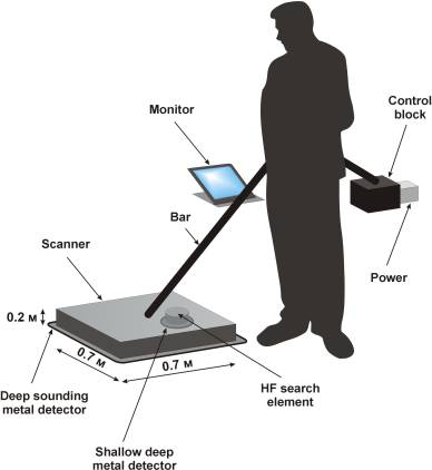
As the above given illustration suggests, the mine detector to
be developed consists of a detection element having both high frequency
(microwave band) and low frequency (induction) channels. Both channels are
employed simultaneously. The operation results of the induction channel are
displayed on the monitor as an image as well. The detection element is placed
inside the square frame of the two-dimensional scanner covered with the
dielectric casing. Images received from both detection channels are processed in
a real-time mode and displayed on the LCD monitor which is mounted on a handle
in front of the operator. The mine detector handle has a counterweight block
accommodating both interface and computer units, as well as a power source.
The minefields are combined as a rule, which means that they include both
antitank and anti-personnel mines. The major part of the mines has round
cross-section view. The antitank mines have diameter of about 300 mm, and the
average diameter of the anti-personnel mine amounts to 75 mm. Some types of the
mines contain practically no metal, which substantially impedes their detection.
In this case the key give-away factor lies in the blasting charges of the mines,
the dielectric properties of which differ from analogous characteristics of the
ground that covers them. Thus, relative permittivity er for the typical
explosives is between 3.5 and 4.0. At the same time dielectric properties of the
ground in the considered frequency range vary within a wide range from 2.6 to
25.0, depending on the composition and moisture content of the ground. The
lowest value of the range is related to absolutely dry sand, which is found in
the desert. In the overwhelming majority of cases er for the ground exceeds the
analogous value for the blasting charge.
MiRascan ground-probing holographic radar that makes it possible to detect
and identify slightly deepened (up to 20 cm) objects by their shape has been
developed in the Remote Sensing Laboratory. The principle of the multifrequency
sounding of the condensed media (construction structures, soils, etc.) was
assumed as a basis of the radar design.
In the initial segment of this work, the mock-up of a wide-span mine detector
MiRascan, which included, in the capacity of a detecting element, a five
frequencies ground penetrating radar receiving signals in two crossed
polarities. The detector's sensor was installed on the cart, which was set in
motion by an operator manually.
In the course of further research, the mock-up of the mine detector MiRascan
underwent modernization. Basic features of it were as follows:
- On the lower flange of the GPR cylindrical antenna, the head of the metal
detector was installed;
- On the upper flange of the radar antenna, a generator metal detector block
was installed;
- On the axes of chassis front wheels of the mine detector the electrical
motors working in the impulse mode were installed;
- Remote control system of the mine detector movement was assembled. The
operator via the remote control box, connected to the cart by the cable of
15 m length, exercises control over the movement of the mine detector.
The radar has five operational frequencies in the range from 1.5 to 2.0 GHz and
transmits unmodulated signals at each frequency. Its signals are received in two
polarizations. Power emitted by the generator on each frequency is switched in
sequence. It amounts up to 10 mW, which provides for the complete safety of
staff. As previously mentioned, the induction loop of the metal detector was
located on the butt end of the antenna of the ground penetrating radar, which
provides spatial coincidence of received images from two channels of the mine
detector. Operating frequency of the metal detector is 2 MHz, and the diameter
of the induction loop is equal to 120 mm. The successive reception of signals on
each frequency and in both polarizations of GPR and from the metal detector is
conducted in the process of scanning the ground surface. The frequency switching
rate is such that it provides for the spatial matching for all microwave images
of the GPR separate frequencies and metal detector image.
The scanning in the lateral direction is carried out at the
expense of electromechanical movement of the SHF device of the radar, and in the
longitudinal direction due to the movement of the entire radar. The scanning
results are displayed in the form of gray scale images on the monitor screen.
Since it is difficult for an operator to perform a simultaneous analysis of all
images on different frequencies, one animated image is formed in which
sequential frames correspond to different frequencies.
The mock-up of the mine detector makes it feasible to survey the lane of
movement 112 cm wide and to display the scanning results on the screen of a
personal portable computer in real time.
The experiments to detect and identify mock-ups of the plastic-cased
anti-personnel and antitank mines were conducted under the full-scale
conditions. The experiments were performed on the special proving ground. The
proving ground had sites with the key types of soils: sand, chernozem, loamy
soil, etc., which ensures wide variation in their dielectric properties.
The mock-ups of the antitank plastic-cased mines of the types of TM-62P3
(manufactured in Russia), TC/6 and TC/2.5 (manufactured in Italy), of the
anti-personnel plastic-cased mines of the types PMN-2 and MS-3 (manufactured in
Russia), as well as of the metallic antitank mines of the types of TM-62M and
PTM-3 (manufactured in Russia) were used in the capacity of the tested objects.
All the mines except the PTM-3 mine had a round cross-section view, and the
PTM-3 mine had a rectangular cross-section.
Wide-span
System for Humanitarian Demining Operations
Introduction.
Our team had
taken an initiative in the development of MiRascan subsurface sounding radar to
enable the operator to detect and identify objects buried under the ground at
low depth (up to 20.0 cm) basing on their shape analysis. The operating
principle of the radar design is based on the method of multi-frequency sounding
of a condensed media (like building structures, grounds, etc.). The method
offered has no counterpart in the world practice so far. (Russians Launch
Anti-Bugging Radar. Microwave Journal, February 1998, Vol. 41, No. 2, pp. 47,
48). The
creators of MiRascan
radar
are Russian Federation Government prize-winners in the field of science and
technology for 1999.
One
of the main problems while liquidating the aftereffects of local conflicts is
mine clearance of the territories that were mined as a result of combat
operations. The special difficulty in the process of humanitarian mine clearance
is presented by the fact that minefields were laid as a rule chaotically,
without compiling proper mine-field records (charts), as well as the fact that
mines with antidisturbance fuses were also installed.
As
a rule, the minefields are combined, which means that they include both antitank
and anti-personnel mines. The major part of the mines has round cross-section
view. The antitank mines have diameter of about 300 mm, and the average diameter
of the anti-personnel mine amounts to 75 mm. Some types of the mines contain
practically no metal, which substantially impedes their detection. In this case
the key give-away factor lies in the blasting charges of the mines, the
dielectric properties of which differ from analogous characteristics of the
ground that covers them. Thus, relative permittivity er
for the typical explosives is between 3.5 and 4.0. At the same time dielectric
properties of the ground in the considered frequency range vary within a wide
range from 2.6 to 25.0, depending on the composition and moisture content of the
ground. The lowest value of the range is related to absolutely dry sand, which
is found in the desert. In the overwhelming majority of cases er
for the ground exceeds the analogous value for the blasting charge.
The
heterogeneities of the surface, as well as a great number of foreign objects in
the ground, especially in the urbanized localities create substantial
difficulties in the mine detection operations. The dielectric contrast of these
heterogeneities with reference to the ground frequently exceeds the contrast of
the plastic-cased mines, which results in an inadmissible level of false alarms.
At the same time, in accordance with the requirements of the UN, the probability
of mine detection should amount to 99.6% at the low level of false alarms. But
these requirements are not met by the existing technical means. Very often the
mine-probing rod and snuffer dogs are the only aids of the sapper.
Description.
The development of the wide
span gears making the most of the spatial filtering to reduce the level of false
alarms is one of the approaches to achieve the set aim. The mock-up of such mine
detector using Russian-made mine detectors of the MMP type in the capacity of
the search elements was designed in late 1980s.
The
new design considers possibilities for the enhancement of efficiency of mine
detection operations that thanks to usage of multifrequency SHF transducers
coupled with metal detector and to generation of the radio images of the terrain
in the lane of movement of a mine detector. An experimental mock-up with the
transducer providing for scanning in two dimensions has been developed, and
algorithms for the representation of information on the display screen in the
form of animated images have been put forward. Proposed methods may find their
use during peacekeeping and humanitarian operations. Fig. 1 presents the
block diagram of the radar MiRascan.
The
scanning in the lateral direction is carried out at the expense of
electromechanical movement of the radar, and in the longitudinal direction due
to the movement of the cart. The scanning results are displayed in the form of
gray scale images on the monitor screen. Since it is difficult for an operator
to perform a simultaneous analysis of all images on different frequencies, one
animated image is formed in which sequential frames correspond to different
frequencies.
The mines were deepened in the ground to the depth of 1 cm for the
anti-personnel mines and to 5-8 cm for the antitank mines. The experiments were
conducted on the two types of soils: heavily moistened sand and heavily
moistened chernozem with turf cover. The soils had the natural moisture content
close to the saturation as the experiments were carried out a day after the long
heavy showers.
 |
 |
|
Diagram of mines arrangement
in the proving ground
|
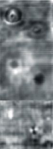
Microwave images of mine mock-ups
in the examined lane with sandy soil
|